Commercial and industrial substation manual (design and construction) EEP
Substation Earthing Typical Installation of Earthing Electrodes 28949 (114kb) Personnel and Equipment Hatch Installation 38630 (214kb) Underground Substation Personnel Access Ladder Mk4 Arrangement 42416 (121kb) Basement Substation Fan Mounting Plate (*Sydney CBD Substation only)
the layout of electrical substation gurugubelli balakrishna the electrical blog
Conduct planning meetings for the new power substation. Perform load flow power studies. Determine the substation size and total footprint required (with equipment), including transmission right of way (ROW). Determine substation configuration (Single Bus, Main/Transfer Bus, Ring Bus, etc.). Allocate required funds for real estate purchase.
Section electric substation dwg file Cadbull
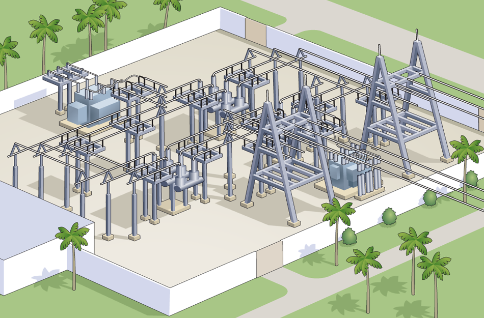
A substation is a part of an electrical generation, transmission, and distribution system. Substations transform voltage from high to low, or the reverse, or perform any of several other important functions. Between the generating station and consumer, electric power may flow through several substations at different voltage levels.
Electrical Substation Layout
Covers the general design considerations, documents and drawings related to designing a substation. Volume II, Physical Layout. Covers the layout considerations, bus configurations, and electrical clearances. Volume III, Conductors and Bus Design. Covers bare conductors, rigid and strain bus design. Volume IV, Power Transformers. Covers the.
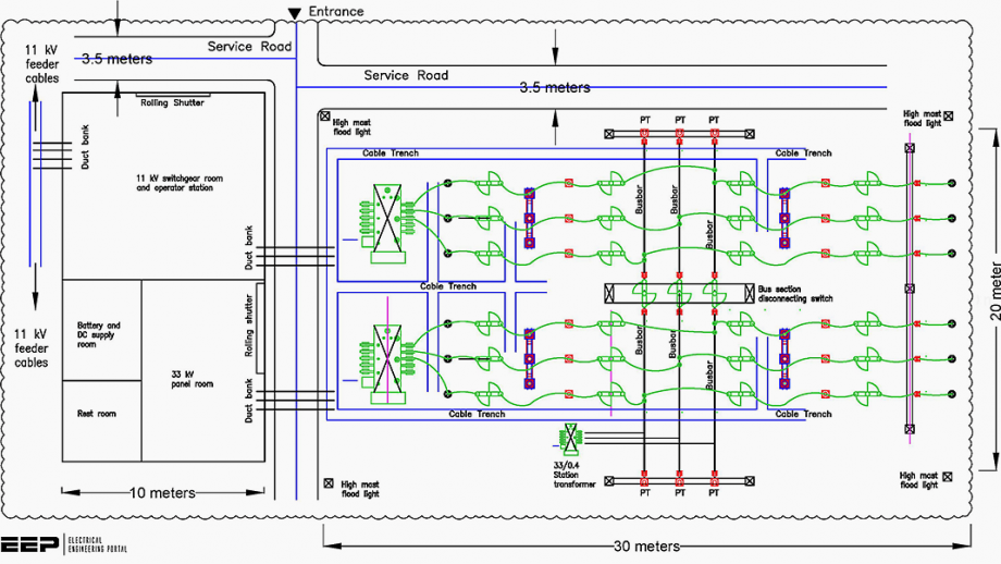
7 typical layout designs of 11kV indoor distribution substation EEP
Conductors in insulated electric cables and flexible cords AS 1746:1991 (R2016) Conductors - Bare overhead - Hard-drawn copper AS 2067 :2016 Substations and high voltage installations exceeding 1 kV a.c. AS/NZS 3000:2007 Electrical Installations (known as the Australian/New Zealand Wiring Rules) AS 3798:2007 + Amdt 1:2008
Layout plan electric substation layout file Cadbull
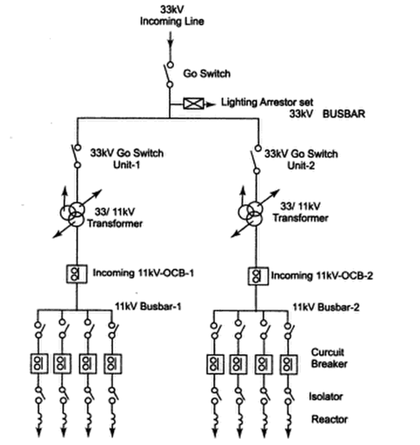
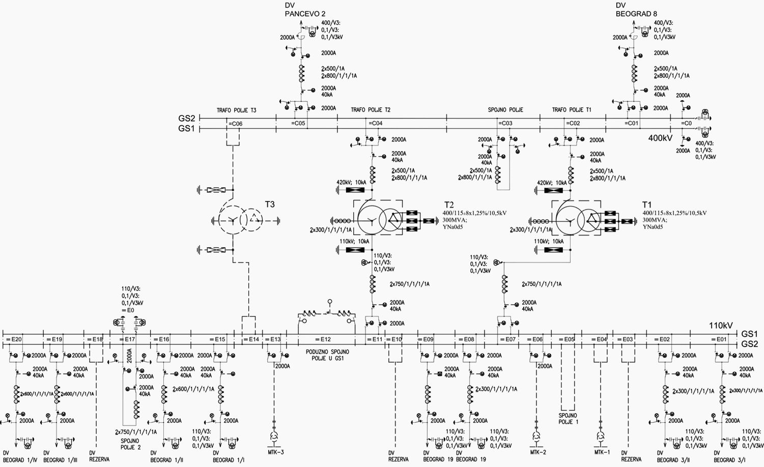
HV substation schematics & diagrams. High voltage power substations are complex networks of power and control connections, represented by design elements like- Single Line Diagrams, layout and block diagrams, schematics, logic diagrams, schedules, and so many more. Wiring diagrams and schematics, in a sense, are the blueprints of electrical design.
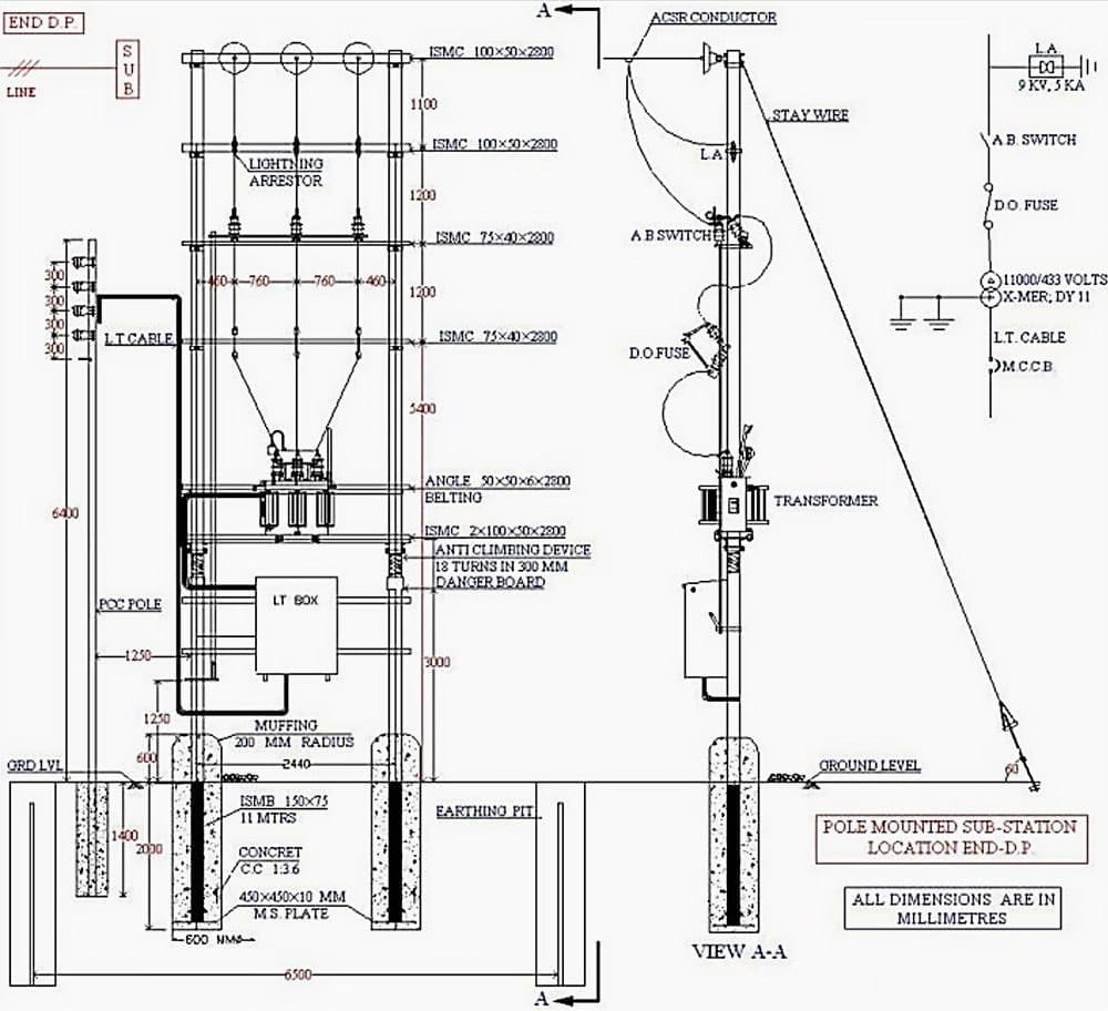
Installation and commissioning of 11/0.43 kV substation EEP
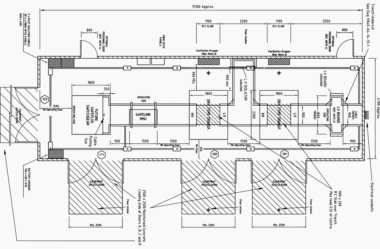
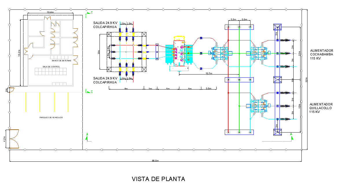
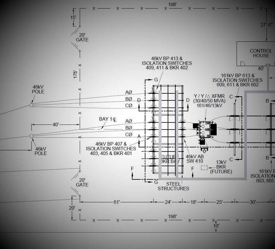
A substation layout diagram is a drawing that shows the arrangement of equipment within a substation. The diagram includes the location of power transformers, switchgear, circuit breakers, and other equipment. It also shows the path of electrical cables andbusbars between the different pieces of equipment.
Basics of Designing Power Substations 3 Phase Associates
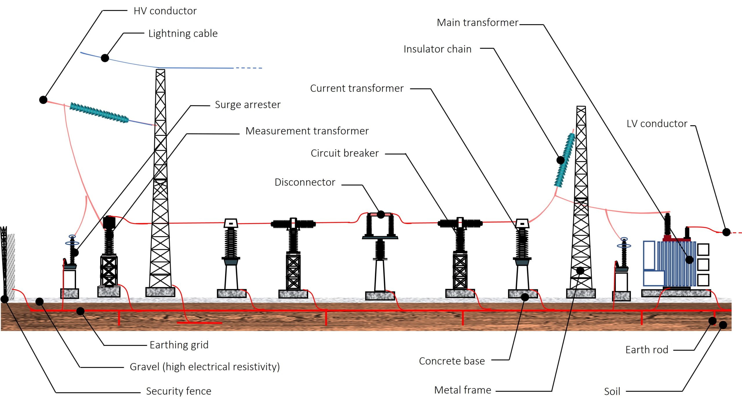
Substation Definition: The electrical substation can be defined as a network of electrical components comprising of power transformers, busbars, auxiliaries, and switchgear etc.
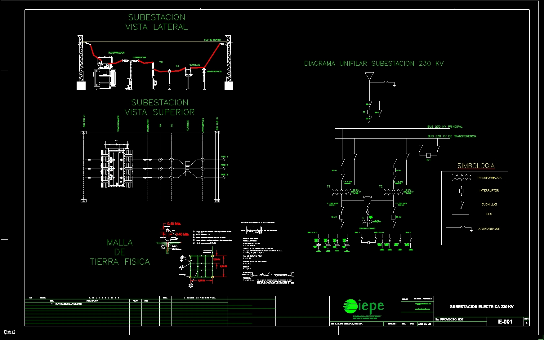
Diagram Electrical Substation DWG Full Project for AutoCAD • Designs CAD
NSP/007/019 - Guidance on Primary Substation Design: Electrical Drawings 3.1. Stage 1 Drawings (Outline) Stage 1 drawings should show the general site layout. This stage should be the initial submission and include the following: 1. Site Layout (Showing overall layout with cable routes, ducts & troughs)
7 typical layout designs of 11kV indoor distribution substation EEP
NS260 Technical Drawings - Sub-Transmission Feeder Earthing. NS264 Technical Drawings - Major Substation Lightning Protection and Insulation Coordination. NS268 Technical Drawings - Specification for Design and Construction of Waterway Crossings. Find the list of Ausgrid network drawings here, including NS114, NS119, NS130, NS177 and more.
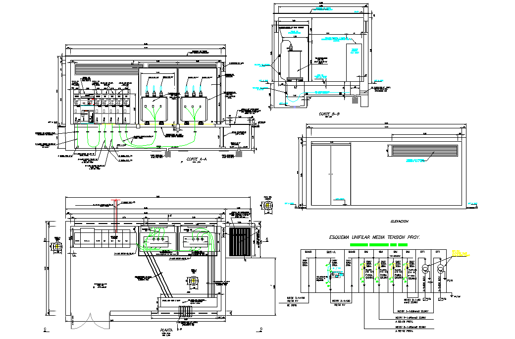
Electrical substations plan and section dwg file Cadbull
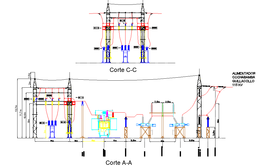
Substation layout diagrams provide scale drawings of the location of each piece of equipment in a substation, in both plan and elevation. While individual utilities may have their own format, there is a high degree of standardization of these types of drawings worldwide, for contractual and tendering purposes.
Electrical Substation Definition, Layout, and Uses of Substations
Associated information and drawings specified in the Design Advice is required tobe based on Specification SDE-001 Substation Electrical Design. These distance take into account typical maintenance work methods s and ensure that the routine and most corrective maintenance tasks can be performed in safe and efficient a manner.
Electrical Substation Layout
Substation Structure Design Guide. Prepared by the Subcommittee on the Design of Substation Structures of the Committee on Electrical Transmission Structures of the Structural Engineering Institute of the American Society of Civil Engineers. Edited by Leon Kempner, Jr. Library of Congress Cataloging-in-Publication Data.
7 typical layout designs of 11kV indoor distribution substation EEP
Transmission substations integrate transmission lines into a network with multiple parallel interconnections, so that power can flow freely over long distances from any generator to any consumer. This transmission grid is often called the bulk power system. Typically, transmission lines operate at voltages above 138 kV.
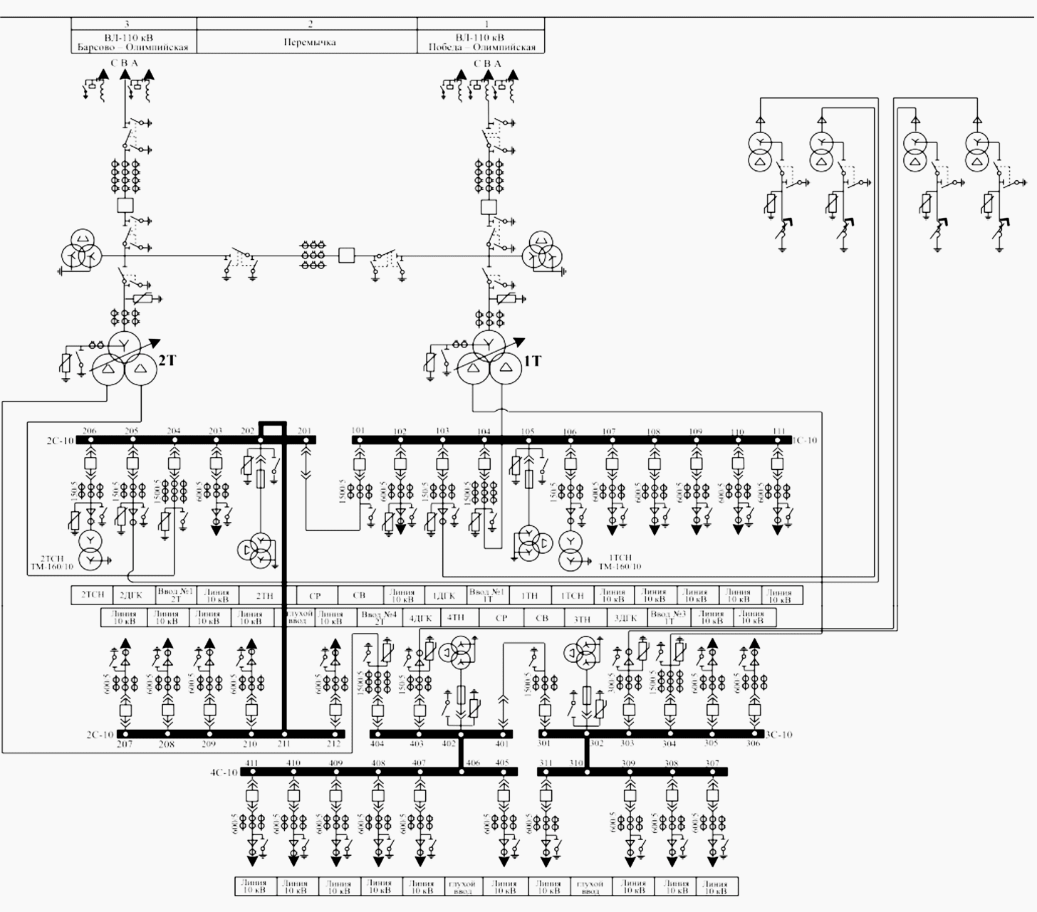
Seven design diagrams that every HV substation engineer MUST understand EEP
The single line diagram (SLD) is the most basic of the set of diagrams that are used to document the electrical functionality of the substation. Its emphasis is on communicating the functions of the power equipment and the associated protection and control system.
Seven design diagrams that every HV substation engineer MUST understand EEP
1. Factors affecting the layout and arrangement of substations Each substation is different in terms of their arrangement and design parameters. First, we will briefly discuss multiple factors that affect the design and layout of a substation. 1.1 Site selection and space constraints