
Symbols for Valves, Pumps and Electrical Equipment on Ship Marine World
The schematic symbol of a pressure relief valve is an essential element that engineers and technicians rely on to identify and interpret the valve's functionality. In this comprehensive guide, we will delve into the different aspects of the pressure relief valve schematic symbol, providing a detailed explanation of its components and their.
Valve Sign Symbols The Engineering Concepts
Types of valves with P&ID symbols. A valve is an element in a piping system that regulates the flow. A rotary valve turns only at 90°. Linear valves operate when the stem is vertical, and the packing box is above. Self-actuated valves keep set-point pressure in pipelines within predetermined ranges.

TU Fluid Power symbols for hydraulic pressure valves.
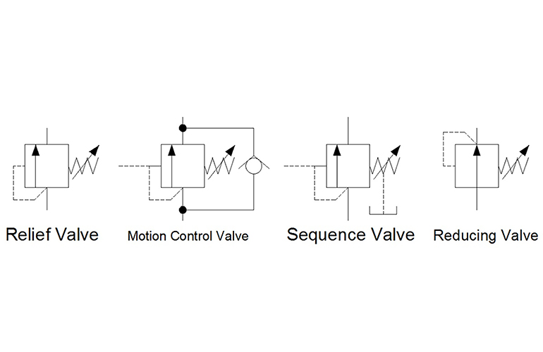
The top symbol indicates a simple, direct operated pressure relief valve. Note how the pilot pressure (shown by the dashed line) comes from the supply line, upstream of the valve. This indicates that as the pressure before the valve increases, it pushes the arrow against the spring and relieves the pressure in the direction of the arrow.

How To Interpret Pressure Valves YouTube
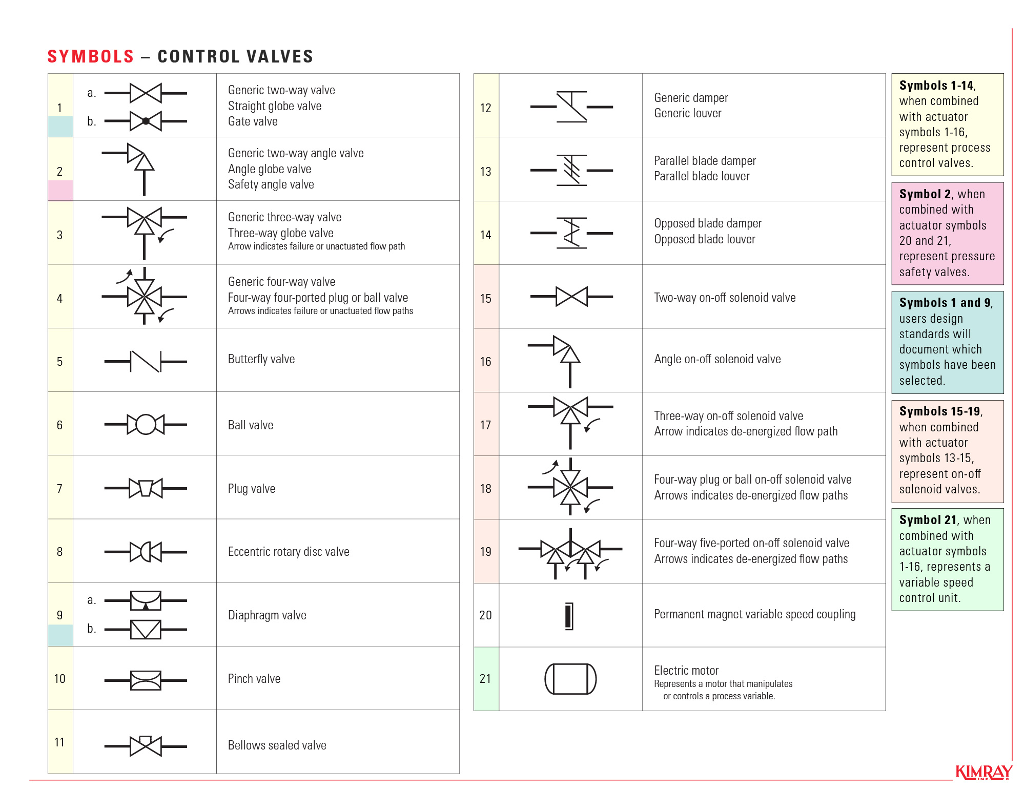
Valve Symbols. 2-Way Valves A 2-way, on/off valve is symbolized by two equilateral triangles that point toward each other. These valves use varying types of lines to represent different types of valves. The direction of the flow is shown by an arrowhead at the end of the line.
Pressure relief valve symbol icon Royalty Free Vector Image
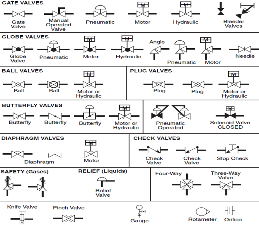
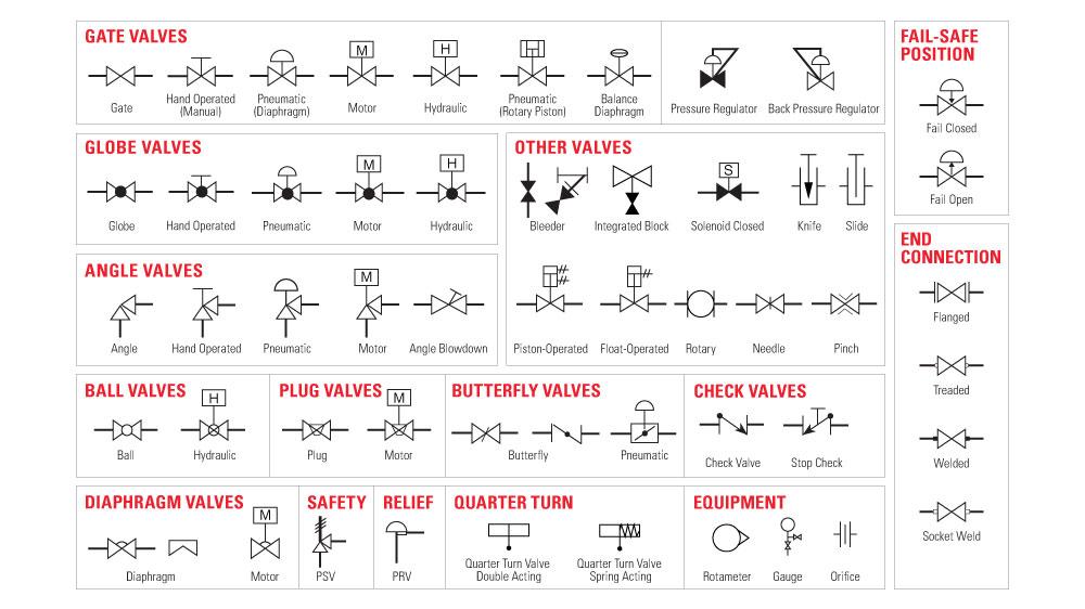
Here is a list of symbols for various types of valves used in process industry. Angle Blowdown Valve Angle Globe Valve Angle Valve Angle Valve Hand Operated Auto Circulation Valve Back Pressure Regulator Balanced Diaphragm Gate Valve Ball Valve Ball Valve Normally Closed Bleeder Valve Butterfly Valve Check Valve 01 Check Valve 02 Control Valve
Valve Symbols
Fluid Power Symbols FLUID POWER GRAPHIC SYMBOLS ANSI Y32.10 GRAPHIC SYMBOLS 1. Introduction 1.1 General. either end of symbol. 7.5 Pressure Compensated 7.6 Electrical 7.6.1 Solenoid (Single Winding) 7.6.2 Reversing Motor 7.7 Pilot Pressure 7.7.1 Remote Supply Page 8 of 24
Pressure Regulator Pid Symbol
Piping and Instrument Diagram Standard Symbols Detailed Documentation provides a standard set of shapes & symbols for documenting P&ID and PFD, including standard shapes of instrument, valves, pump, heating exchanges, mixers, crushers, vessels, compressors, filters, motors and connecting shapes. Or Gate Not Gate Correcting Element Diamond
Pressure relief valve symbol icon Royalty Free Vector Image
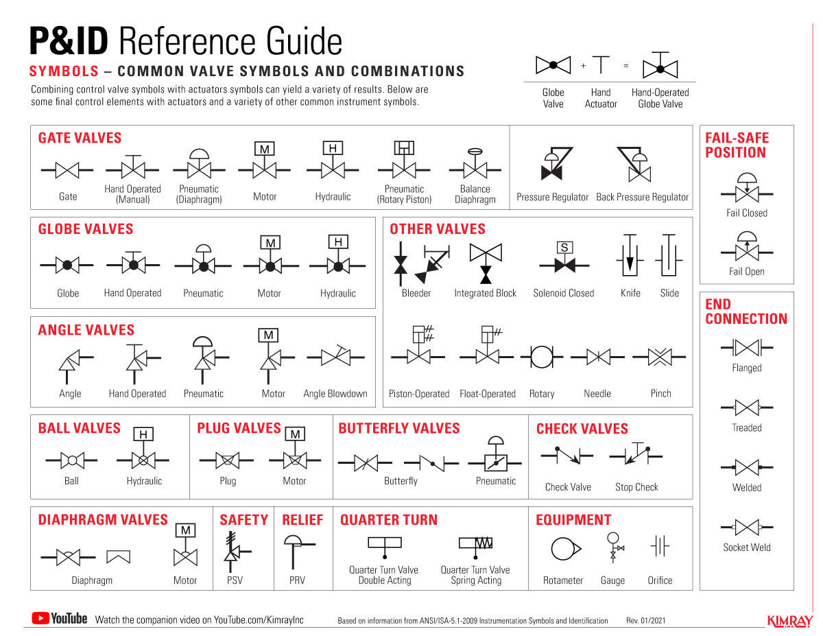
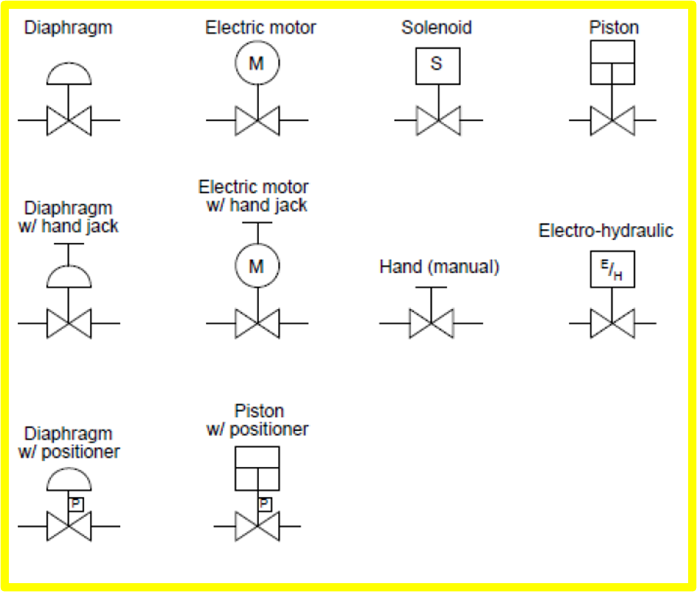
In each process and instrumentation diagram, valves have specific symbols that make them easy to recognize. The symbol typically consists of the actual valve symbol, and the actuation method such as pneumatic, hydraulic, or electric. Table of contents How do I read valve symbols and P&ID diagrams? Valve symbols Valve states Actuator type symbols
Pressure Regulator Pid Symbol
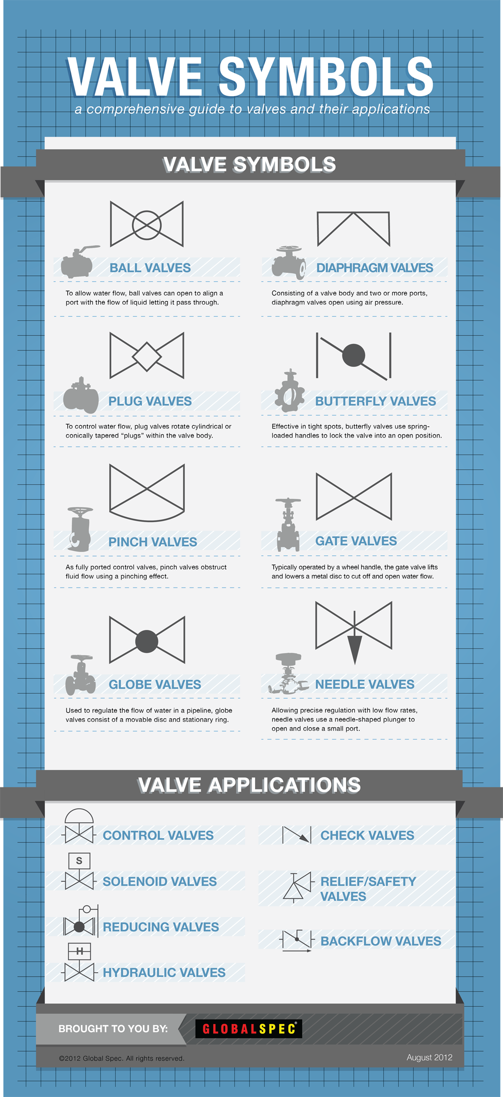
valve is a mechanical device that controls the flow of fluid and pressure within a system or process. valve controls system or process fluid flow and pressure by performing any of the following functions: Stopping and starting fluid flow Varying (throttling) the amount of fluid flow Controlling the direction of fluid flow

Types Of Valves, Their Functions And Symbols Engineering Discoveries
WHAT IS P&ID? P&ID is the acronym for "Piping and instrumentation diagram", i.e. a very detailed diagram showing the processes happening within a plant, the involved equipment, and their interconnections. A set of standardized P&ID symbols is used by process engineers to draft such diagrams.
The Most Common Control Valve Symbols on a P&ID Kimray
A pressure relief valve is a NC (normally closed) type safety valve which operates when system pressure increases above a maximum working pressure. The normally closed position is indicated by the arrow away from the center line. The dashed line indicates that the system pressure acts against spring force for valve actuation.

Industrial Valve and Actuator Symbols Process Control Solutions Blog
Valve symbols are used to signify the pressure, flow and direction of fluids through a valve. These illustrations, commonly referred to as Piping and Instrumentation Diagram (P&DI) symbols, may vary slightly between organizations but similar sketches are used to identify types and position of valves.

Valve Symbols in P&ID Ball Valve, Relief Valve and more
Hydraulic symbology 203 - pressure valves. By Josh Cosford | March 21, 2019. In Hydraulic Symbology 101 ( read it here first ), I covered the basic square used for pressure valves and also showed the most stripped-down versions of the two most commonly used pressure valve symbols, the relief valve and the pressure reducing valve. In this.
Pressure Relief Valves An Exploration of Industrial Technology
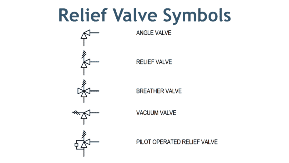
P&ID Quiz - Test yourself, Take This Quiz Relief Valve Symbols Here in the image above, the first symbol is of angle valve. In most cases, a globe valve is used as an angle valve. The next symbol is the relief valve used to protect the piping system or equipment from overpressure. Now the breather valve is used on the cone roof tank.
Control valve symbols in P&id Valves Industrial Automation, PLC
The generic symbol for a 2-way valve is two triangles pointing to each other with the tips of the inner points touching. The pipe lines are represented by lines connecting to each side of the valve symbol. Various types of lines are used to represent different pipes, tubes, and hoses.
Hydraulic symbology 203 pressure valves
A valve is a device that regulates, directs or controls the flow of a fluid (gases, liquids, fluidized solids, or slurries) by opening, closing, or partially obstructing various passageways. Valves are technically fittings, but are usually discussed as a separate category.